Upper Kotmale Hydro Power Station (UKHP)
This is the latest hydro power plant which joins to the
Mahaweli complex and located at Niyamgamdara. UKHP is the 3rd
largest hydro power plant in Sri Lanka and it has the longest tunnel (with
penstock). This is one of the underground power stations in Sri Lanka and this
feeds 150 MW to national grid. There are some special features like electrical
breaking, remote control and flood forecasting system in this run-off river
type power plant. There are 2 Fransis type turbines which are covered by spiral
casings were used to generate electricity. The dam and the reservoir is located
in Thalawakale area and the catchment area of the power plant is “Agra Oya” and
“Nanu Oya”. Generating voltage of UKHP is 13.8 kV. This is stepped up to 220 kV
and connects to the Kotmale switch yard using double circuit transmission lines
and then to Biyagama grid. And also UKHP has head of 473m. In upper Kotmale
power plant use Francis type Turbines. Upper Kotmale power plant was Japanese
funded project. This was JAICA Loan and Constructor and Consultant both are
Japan.

Reservoir and Dam
 |
| Dam |

This is a run-off river type
hydro plant. Therefore this is actually not a reservoir, it is called
regulating pond. This concrete gravity dam consists of 5 radial type spillway
gates one with a flap gate. St.Clair waterfall is taking water from this pond. Therefore
there is another gate for release water for the waterfall. Details of the dam
and gates are as follows.
·
Height of
the dam = 33.5 m
·
Length of
the dam = 180 m
·
Width of
the dam = 7 m
·
Catchment
area = 310 km2
·
Max.
Spillway capacity = 660 m3/s
·
Spill Level
= 1194 m
·
Minimum
Operating level = 1190 m
·
Effective
Storage = 0.8 MCM
· St. Clair discharge = 1.3 m3/s
5 spillway gates are used because the storage
capacity is very small compared with others. Area of a gate is 12 x 10 m2 and
weight of a gate is 90 tons. Each gate consists of 2 hydraulic cylinders. When
the water level rises suddenly all these gates are operated according to a
sequence. Flap gate is used to control the water level of the pond. There are 2
types of sensors used to indicate the water level to the control room. Either
pressure sensor or floating sensor will give an indication to the control room
and then the flap gate or spillway gates may be open.
Floater is connected
to the gear mechanism and there is an Analogue to Digital converter. The
digital output is then goes to the control as a PLC input.
Intake gate is used to
take water in to the headrace tunnel from the pond and it is always kept open
and holds on two steel bars to avoid the load coming to the hydraulic cylinder.
This is a steel fixed wheel type gate with height of 8.8 m and span of 5 m. The
gate can be operated both local and remote modes. Normal operating speed is 0.3
m/min, but in an emergency case it can be increased to 3 m/min
 |
| Spill gate & Flap gate |
Headrace tunnel and Penstock
This is a horseshoe
shaped type concrete tunnel with total length of 13.8 km with the penstock. The
tunnel has uniform diameter of 5.8 m and 400 mm thickness. Circular steel lined
penstock has length of 793 m and the pressure is 5 MPa. This penstock inclines 480 from
horizontal and has 4 different diameters from headrace tunnel to main inlet
valve.
Surge Chamber
There are different types of surge tanks. They are,

In UKPS used two surge tanks one is upstream and other is
downstream. Upstream surge tank is restricted orifice type and has the diameter
of 12 m.
§
Upstream surge tank
Sudden closing of guide vanes make reverse surge along the
penstock. It didn’t damage to the penstock, because penstock made out of steel.
But surge can damage to the headrace tunnel. So upstream surge tank used for
protection of headrace tunnel. (Water hammer effect)
§
Downstream Surge tank
Used to protect draft tube and turbine from surge build
because of the tailrace water flow behaviors.
Main Inlet Vale (MIV)
|
|
Surge chamber is built to minimize the water pressure due to sudden closing
of Main Inlet Valve (MIV). Upstream surge chamber is restricted orifice type
and has the diameter of 12 m. MIV is used to control the water flow to guide
vanes of the turbine. It is spherical type and it will take 90 s to open or
close and operates using a servo motor (both open and close operations). There
are two seals as service seal (downstream sealing ring) and maintenance seal
(upstream sealing ring) to prevent water leakages after MIV is closed, they are
operated by the high pressure of water path.
 |
| Main Inlet Vale (MIV) |
Turbine
UKHP has 2 Fransis
type vertical shaft hydraulic turbines. This turbine consists of runner,
spiral case and guide vanes (also called Wicket gates) and draft tube. The tail
race is open to the Kotmale reservoir. Rated speed of the turbine is 600 rpm.
There are 20 guide vanes used to control the water flow and 20 stay vanes to
control water flow equally to turbine blades. So all vanes should be operated
to the same angle. For this operation all vanes are connected each other by a
ring. If the only one vane will be stucked all vanes will be stucked due to the
mechanical ring mechanism. To prevent this issue there is an overload pin for
each and every vanes. Then stucked guide vane will be isolated from the
operation. Net head is 473m
and head loss is 19m for both turbines. Discharge rate is 36.9 m3/min
for both machines and output is 77 MW. Water comes perpendicular to the shaft
and leaves parallel to the shaft. Turbine materials are Cr and Ni.
Bearings

As Engineers said both
Pelton and Fransis type turbines are suitable for UKHP. Pelton type turbines
can be kept at atmospheric pressure but Fransis turbines should be
submerged. But there is a future
plan to increase the height of Kotmale dam. Due to the height increment of
Kotmale dam the water level at the tailrace can be increased. Therefore a
Fransis turbine has selected for UKHP.
All to gather there are 3 bearings. They are two guide
bearings and one thrust bearing. One
guide bearing and thrust bearing situated in upper part of the rotor. One guide
bearing situated in lover part of the rotor. In upper Kotmale there is special
type of thrust bearing. The material is PEEK (Poly Ether ketone). In PEEK there
are some advantages. They are hard, low friction Co-efficient and insulation
resistance is high. There are 3 types of bearing arrangement for Francis type
turbines.

Generator

Continue Rated Output : 88 MVA
Rated Voltage at stator terminals : 13.8 kV
Rated Current : 3682A
Rated frequency : 50 Hz
Rated Power Factor : 0.85
Rated Rotation Speed : 600rpm
Max. Runaway speed : 1050rpm
Excitation voltage of 150 VDC is provided
through carbon brushes. The output of the generator is taken for the station
service transformer and the for the excitation transformer before the GCB
(Generator Circuit Breaker). The generator output terminals from generator to
main transformer are made through Isolated Phase Bus (IPBS- this is an air
insulated Cu bar).

Rotor
There are 28 carbon brushes in rotor. Due to friction
brushes are ablated. When the carbon brush length is become 30 mm it should be
replaced by 70 mm brand new brush.


Generator Braking
There are two type of breaking use in Upper
Kotmale power station. Electrical breaking and Mechanical Breaking.
1)
Electrical Braking
To stop the generator rapidly they used electrical braking
system. When the generator slows down to 50% of its rated speed (at 300 rpm)
electrical braking is applied. The thing happens in that case is three stator
phases are short circuited and earthed.
2)
Mechanical Breaking
Electrical braking reduce speed slowly. To stop the machine
rapidly we use mechanical braking. When the generator slows down to 5 % of its
rated speed (at 30 rpm) mechanical brake is applied by a pressurized air
system.
Governor control
There are mainly 2 parameters in governor; power setter
(65P) and load limiter (77). Power setter controls the extent of opening of
guide vanes. In UKHP when it opens 80%, we can get the 75 MW output. Load
limiter gives the upper level of guide vane opening.

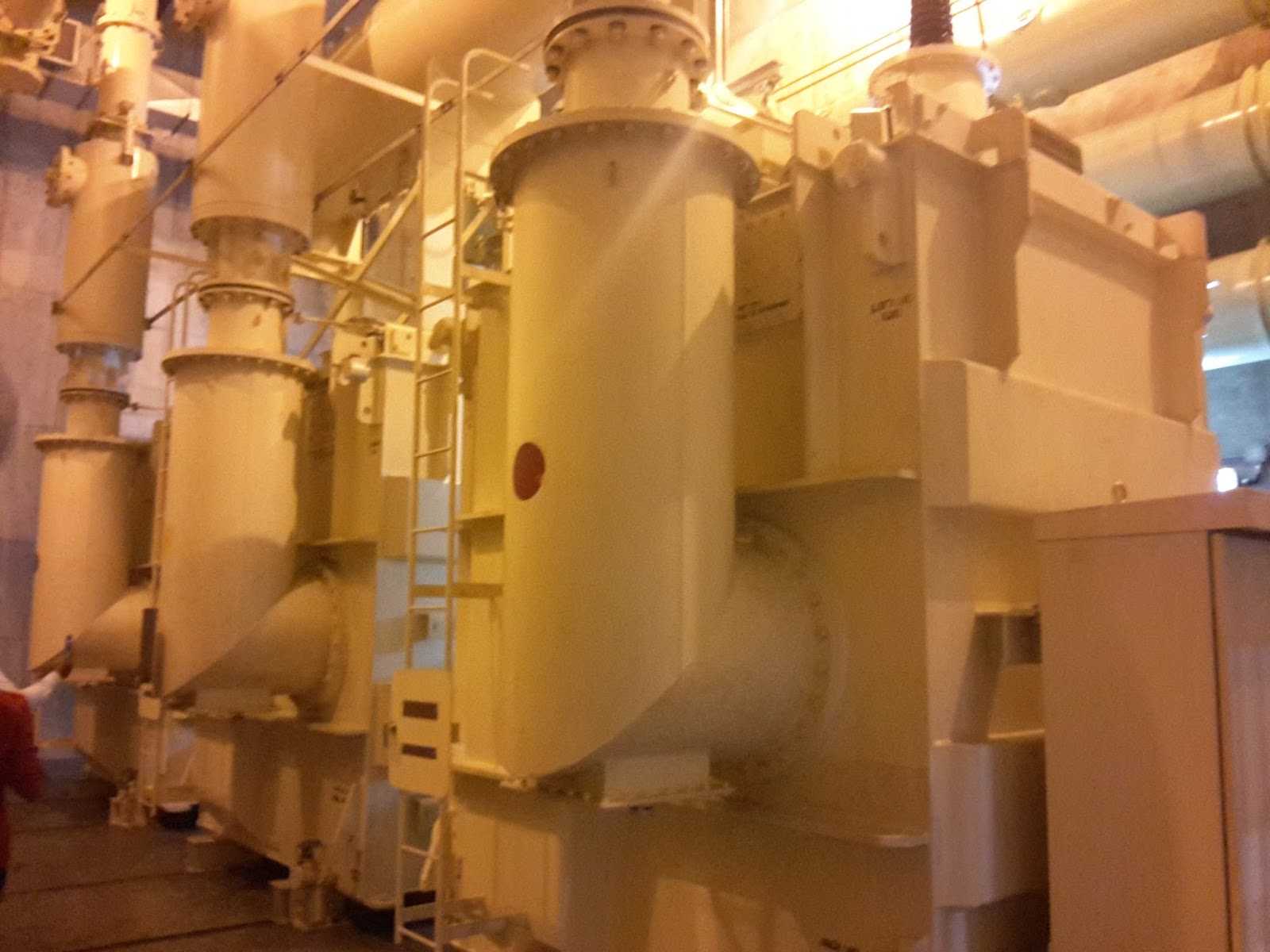
Transformer
There are two numbers of special type main transformers in
the UKHP for two generator units. A transformer unit consists of three single
phase transformers with common conservator tank. All three phases are immersed
in same oil system. Therefore the transformer is more compacted. Ratings of
transformers are as below.
Capacity :
88 MVA Voltage
ratio :
220 kV / 13.8 kV
LV current :
3682 A HV
current : 231 A
Vector
Group :
YNd11
These are core type transformers and each one has a seven
number of HV tap positions. A Transformer only has an off load tap changer.
Transformer oil is water cooled. Transformer conservator tank has a rubber cell
to separate the inside oil from the outside air. Both transformers equipped
with online gas analyzers to analyze the faults occur inside the transformers.
The sensor of this system is sensitive to Hydrogen (H2), Carbon
Monoxide (CO), Ethylene (C2H4) and acetylene (C2H2)
which are the primary indicators of inside faults of oil filled transformers.
LV side of the transformer is connected to generator through Isolated Phase Bus
and HV side is connected to GIS system through Gas Insulated Bus. Isolated
Phase bus is filled with atmospheric air due to low voltage and Gas Insulated
Bus is filled with SF6.


Thanks.This post very help for me.
ReplyDeleteincluding lot of information. thank you
ReplyDelete